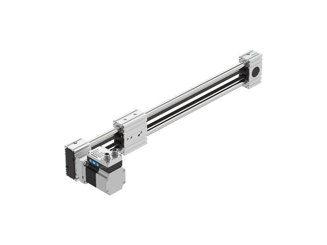
Festo ELGE-TB-35-500-0H-ST-M-H1-PLK-AA-AT-FR Toothed Belt Axis Unit
Electromechanical axis with toothed belt, recirculating ball bearing guide, 500mm stroke, PNP and IO-Link bus protocol and activation, Top cable outlet, and Front right motor position . View other configurations.

- ELGE-TB-35-500-0H-ST-M-H1-PLK-AA-AT-FR
- 8083935
- ELGE-TB-35-500-0H-ST-M-H1-PLK-AA-AT-FR
- By Festo
- FREE Shipping
Overview
Features
- 18.46MM effective diameter of drive pinion
- 500MM working stroke
- 35 size
- 0.094% toothed-belt stretch
- 2MM toothed-belt pitch
- Horizontal mounting position
- Recirculating ball bearing guide guide
- Electromechanical linear axis design
- With toothed belt design
- With integrated drive design
- Stepper motor type of motor
- 997293 symbol
- Motor encoder position detection
- Via proximity switch position detection
- Positive fixed stop block referencing
- Negative fixed stop block referencing
- Absolute single-turn encoder rotor position sensor
- Magnetic rotor position sensor, encoder measuring principle
- Switch-off for excessive temperature temperature monitoring
- Integrated precise CMOS temperature sensor with analogue output temperature monitoring
- User interface additional functions
- Integrated end-position sensing additional functions
- LED display
- LED ready status indication
- 8.5MS2 max. acceleration
- 1.2M/S max. speed
- ±0.1 mm repetition accuracy
- Configurable features of digital logic outputs
- Not galvanically isolated features of digital logic outputs
- 100% duty cycle
- B insulation protection class
- 100MA max. current digital logic outputs
- 5300A max. current consumption
- 0.3A max. current consumption, logic
- 24V nominal voltage dC
- 5.3A nominal current
- IO-Link parameterisation interface
- User interface parameterisation interface
- 16BIT rotor position transducer resolution
- +/- 15% permissible voltage fluctuations
- Plugs power supply, connection type
- M12x1, T-coded according to EN 61076-2-111 power supply, connection system
- 4 power supply, number of pins/wires
- 995989 power supply, connection pattern
- RCM trademark approval
- KC-EMV kC mark
- To EU EMC Directive cE mark (see declaration of conformity)
- In accordance with EU RoHS Directive cE mark (see declaration of conformity)
- To UK instructions for EMC cE marking (see declaration of conformity)
- To UK RoHS instructions cE marking (see declaration of conformity)
- Transport application test with severity level 2 to FN 942017-4 and EN 60068-2-6 vibration resistance
- Shock test with severity level 2 to FN 942017-5 and EN 60068-2-27 shock resistance
- VDMA24364 zone III lABS (PWIS) conformity
- 0 - 90% relative air humidity
- IP20 degree of protection
- III protection class
- 0GC ambient temperature
- 50GC ambient temperature
- Power must be reduced by 2% per K at ambient temperatures above 30°C. note on ambient temperature
- 3770Y12 2nd moment of area iy
- 4190Y12 2nd moment of area iz
- 50N max. force fy
- 50N max. force fz
- 2.5NM max. moment mx
- 8NM max. moment my
- 8NM max. moment mz
- 50N max. feed force fx
- 2.8KG reference value effective load, horizontal
- 58Y13 feed constant
- 5000KM reference service life
- Life-time lubrication maintenance interval
- 0.31G additional moving mass per 10 mm stroke
- 3740G product weight
- 2 number of digital logic outputs 24 v dC
- 2 number of digital logic inputs
- Based on IEC 61131-2, type 1 specification logic input
- 24V working range of logic input
- Yes iO-Link, sIO-Mode support
- Configurable features of logic input
- Not galvanically isolated features of logic input
- Device V 1.1 iO-Link, protocol version
- COM3 (230.4 kBaud) iO-Link, communication mode
- A iO-Link, port class
- Device 1 iO-Link, number of ports
- 2 bytes iO-Link, process data length oUT
- Move in 1 bit iO-Link, process data content oUT
- Move out 1 bit iO-Link, process data content oUT
- Quit Error 1 bit iO-Link, process data content oUT
- Move intermediate 1 bit iO-Link, process data content oUT
- 2 bytes iO-Link, process data length iN
- State In 1 bit iO-Link, process data content iN
- State Out 1 bit iO-Link, process data content iN
- State Move 1 bit iO-Link, process data content iN
- State Device 1 bit iO-Link, process data content iN
- State Intermediate 1 bit iO-Link, process data content iN
- 32-bit force iO-Link, service data iN
- 32-bit position iO-Link, service data iN
- 32-bit speed iO-Link, service data iN
- 1 ms iO-Link, min. cycle time
- 500KB iO-Link, data storage required
- 15 m outputs max. cable length
- 15 m inputs max. cable length
- 20 m with IO-Link® operation max. cable length
- PNP (positive switching) switching logic for outputs
- PNP (positive switching) switching logic for inputs
- Plugs iO-Link, connection technology
- Plug logic interface, connection type
- M12x1, A-coded according to EN 61076-2-101 logic interface, connection technology
- 8 logic interface, number of pins/wires
- 992264 logic interface, plug pattern
- Profile mounting type of mounting
- Anodised wrought aluminium alloy material profile
- RoHS-compliant note on materials
- Anodised wrought aluminium alloy material drive cover
- High-alloy stainless steel material pulleys
- Anodised wrought aluminium alloy material slide
- Beryllium bronze material toothed belt clamping piece
- Polychloroprene with glass filament and nylon coating material toothed belt
- -20GC to 60GC storage temperature
Documents
Accessories
Mounting Accessories
Electrical Accessories
Cylinder Mountings
Proximity Sensors
Need Help? Call an engineer at 1-802-880-3123
We're open Mo-Th 8am to 5:30pm. Fr 8am to 5pm ET


